| First & Third Angle projections |
How to draw objects or components |
Working drawings for buildings |
|
| Types of lines | Sketching techniques | Lettering | |
This paragraph is concerned with the production of drawings. Specifications and working drawings convey to the contractor/builder the necessary information to erect and complete a structure. Drawings will vary from company to company but the following approach is used for this subject:
- Identify and analyse the assignment instruction to ensure you have a complete view of the scope of work.
- If you have any question clarify the issues with your lecturer.
- Think of possible solutions to all aspects of your assignment and make, if necessary, freehand multi-view and/or pictorial sketches for clarification.
- You should then discuss your ideas with your lecturer.
- If you have a clear understanding of the scope of work you may then prepare your draft sketches as outlined below.
In Builders Working Drawing you learn how to create orthographic drawing as well as pictorial drawings.
First and third angle projection
This is a graphical method used in engineering drawings.
The word orthographic is derived from the Greek words orthos-straight,
rectangular and graphos-written, drawn. A drawing of
a structure or part thereof can be drawn using the following projection
methods:
(a) orthogonal
(b) oblique and/or (c)
perspective
There are two methods of drawing orthographic projections:
1) first angle projection and 2) third angle
projection
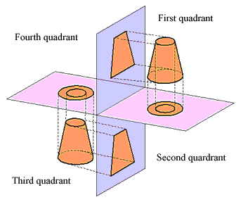
They are based on right angle planes with defined separate spaces , or quadrants. Each quadrant could obtain an object to be presented. However, only two are commonly used, the first and the third as shown in Figure 1.
 Both systems
of projection are approved internationally and the system used is clearly
indicated on all engineering drawings with the following illustrations:
Figure 1 Figure
2
In which projection architectural and builders working drawings are represented is generally insignificant. Nearly all of those drawings do not indicate in which projection they are drawn and it really does not matter. However, it is important that you understand the basic principles of orthographic projection and be able to construct orthographic views of objects.
[ top ]
 Figure 3 |
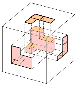
The easiest way to explain the development of a orthographic drawing is to place an object in a glass cube as shown in the opposite figure. The object surfaces are then projected on the faces of the cube. The cube like any card box can be unfolded so that all six surface areas are shown as blow.
|
Figure 5 shows the unfolded box with the same object as shown in Figure 3.

Figure 5
[ top ]
How to draw objects or components
Adopt the method below for drawing building objects or components.

Figure 6 |
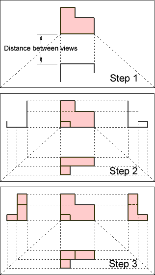
Choose which view or direction or face will be used as the font view of the object or component. The object or component you chose for the front view should have the longest straight edge.. From the bottom edge of the front view draw feint construction lines @ 45° as shown in Step 1 Carry on finishing the top view. Start a line below the front view with sufficient distance for dimensioning of the object or component. Complete the top view Use faint construction lines and draw the outline of the side views as shown in Step 2 Complete the side view with the aid of construction lines as shown in Step 3 Always use this method for drawing objects or components. |
In Drawing 1 you will draw a number of different objects. The views should always be aligned with each other allowing sufficient space between the views for dimensions (see Step 1 - Figure 6). Lines that cannot be seen in a specific view are hidden and shown as dashed lines.
Working drawings for buildings
Orthographic building/construction drawings are a two dimensional representation of a structure. They are drawn in various scales depending on the detail and content required and offer the following advantages compared with other systems:
- It's usually the simplest and quickest method of giving an accurate representation of an object.
- Only those views that are essential need to be drawn.
- Dimensioning is relatively easy.
- Sectional and part views are easier to construct.
The only disadvantage of this method is that some training is necessary before you can draw or read a drawing. Sometimes it's easier to draw the object in perspective view (pictorial view), especially for clients who have difficulties interpreting orthographic drawings.
Building construction drawings usually show the following views:
- Plan view (Floor-plan)
- Elevations (faces of the building)
- Cross-Sections
- Details
a) Site plan, b) floor plan(s), c)elevations, d) Sections
All your drawings must be fully dimensioned to enable builders to construct and build the drawn object.
To draw a complete set of plan for a building do the following:
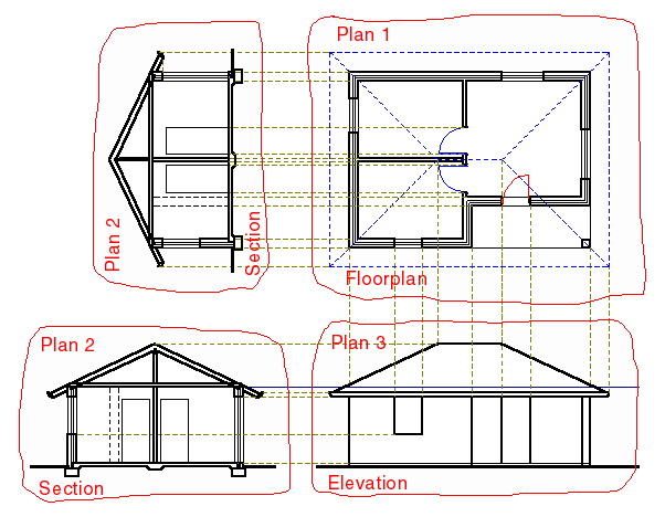
- First draw a plan-view in pencil on any paper (Plan 1)
- Then draw the section (Plan 2) on another piece of paper. Use Plan 1 to extend the lines and add all vertical elements that cannot be shown in a plan-view to finish the Section.
- Use Floor plan (Plan 1) and the rearranged Section (Plan 2) to draw the Elevation (Plan 3) as shown below.
- Keep section (Plan 2) and rotate Plan1 90° (clockwise or anticlockwise) and draw another elevation.
- Rotate Plan1 again 90° to complete the next elevation.
- Use the same procedure to complete all elevations.
- Having finished drawing all required items you can now arrange all items and place them on your board to fit the designated paper size. Then overlay the transparency paper and trace all views.

All drawings, whether section, details, pictorial views etc. that need to be produced in ink on transparency paper draw first the item on any paper and then trace it onto the transparency paper. This allows you to place the items most appropriately on your designated sheet avoiding running out of space or overcrowding.
[ top ]
Type of lines
If all lines on a drawing are of the same thickness the drawing may not
be clear or difficult to interpret. However, if the salient features are
shown in thick lines and others in thin lines the drawing is easier to
read and interpret. To ensure uniformity of line types the Australian
and international standards should be used [see ARCHITECTURAL DRAWING
Standards & Conventions (K J Holtom)].
The most common sizes for pens are 0.7, 0.5, 0.35 and 0.25 mm. The minimum
requirements is to have two disposable pens, sizes 0.4 and 0.2 mm. (Disposable
Rotring pens are not recommended because of slow drying.)
If you need to draw a thicker line, the back-line technique can
be used. This line is produced by drawing two (2) lines at approximately
line distance apart (with a 0.4 mm pen a 0.7 mm line thickness can be
produced).
Pencil lines should be sharp, dense and uniform on drawings that
are not produced in ink. Make sure their is a visible contrast between
the thickness of thick, medium and thin lines. This can be achieved by
using a softer grade for thick lines than that used for the other line
thickness. As a guide use for construction and dimension lines a 2H-lead,
for all other thin lines a H-lead and for thick lines B- or HB- lead.
Smudging of pencil drawings can be avoided if you cover the finish portion
of the drawing with a piece of paper.
Sketching techniques
Most students may not have to produce complete working drawings in their
working environment. However, it will be beneficial if you develop good
freehand sketching skills. The ability to create detailed views with a
pencil on a piece of paper is extremely important for supervisors or builders.
All details are composed of lines: horizontal, vertical, angular, circular
or elliptical. The procedure below describes the movement of your hand
for sketching lines. A bit of practice is needed to develop the skill
to produce freehand sketches.

Figure 8
[ top ]
To "letter" a drawing or sketch in a neat and consistent style is very
important. Bad lettering will spoil your drawing. Use single stroke vertical
or sloping letters on your drawing.
For all letters we use only upper case. Normal lettering is made 3 mm
high with 2 mm line spacing and titles 5 mm high with 3 mm line spacing.
Good lettering depends on the following:
- Uniformity of shape (refer to ARCHITECTURAL DRAWING
Standards & Conventions (K J Holtom)
- Uniformity of style (no mixed style on the same drawing)
- Uniformity of size (letter touching upper & lower guide lines)
- Uniformity of line thickness (all strokes & curves must have the same line thickness)
- Uniformity of slope (use vertical or sloping guide lines to keep characters upright or sloping)
- Uniformity of spacing (keep white areas between letters equal and the space between words the same)
To produce good lettering the position of your hand is important. Use the following guidelines as a basis:
- Your forearm should rest on the drawing board
- Your index finger should be kept as straight as possible along the pencil. This will help to avoid tension in the hand.
- Your forearm should be at an angle of 75-80° with the line of lettering.
- All strokes should where possible be made from top to bottom and from right to left.
Pencil lettering
The most important aspect of pencil lettering is making a uniform dense
black line by applying adequate pressure on the pencil. This depends on
selecting a pencil that has the proper hardness. The selection of the
grade (B, HB or H) depends on the surface of your drawing paper. Try the
different leads for best result!
Ink lettering
In ink lettering the thickness depends on the pen used and not on the
pressure applied. If you use tubular pens you should hold them perpendicular
to the paper to avoid varying line thickness.
[ top ]
